DESCRIPTION
The process cycle test is a technique that is applied in particular to the testing of the quality characteristic of
Suitability (integration between the administrative organisation and the automated information system). The test basis
should contain structured information on the required system behaviour in the form of paths and decision points. The
process cycle test digresses on a number of points from most other test design techniques:
-
The process cycle test is not a design test, but a structure test: the test cases issue from the structure of the
procedure flow and not from the design specifications.
-
The predicted result in the process cycle test is simple: the physical test case should be executable. This checks
implicitly that the individual actions can be carried out. In contrast to other test design techniques, no explicit
prediction is made of the result, and so this does not have to be checked.
The process cycle test focuses on the coverage of the variations in the processing. The basic technique used in this is
Paths: test depth level 2.
Variations on the process cycle test can be created by applying the basic technique Paths: test depth level 1, test
depth level 3 and higher. With this, paths can be tested in respectively more or less depth.
POINTS OF FOCUS IN THE STEPS
In this section, the process cycle test is explained step by step, taking the generic steps (see Test Design Techniques) as a starting point. An example is also set out, showing at each step how the technique works.
In the example, a certain drawing technique is used to represent a detailed process diagram. Since no uniform
agreements exist concerning the use of the technique and the use of the symbols, the meanings of the symbols are stated
next to the diagram.
Example 1 - Claim forms come into the claims handling department. After someone in the
department has entered the claim details into the system, a process is begun to check the completeness of the details.
In the event of incompleteness, the employee contacts the insured party, after which the details can be re-entered.
When the details are complete, a process is begun to determine the claim sum and the number of claims submitted by the
insured party over the previous year. If the claim sum is higher than €2,500, or if in the previous year more than 2
damages claims have been submitted, the head of the department then assesses whether or not the claim should be met. In
the event of rejection by the head of department, a rejection letter is created; if it has been approved, a letter of
approval is created. With 2 or fewer claims in the previous year and a damages claim of €2,500 or less, a letter of
approval is always created.
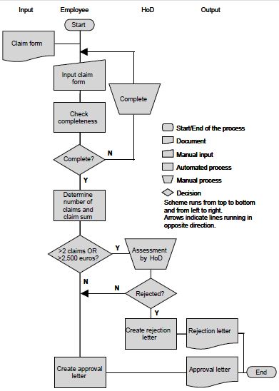
Figure 1: Part of the detailed process diagram of “claims handling”.
Below, it is set out per step how the process cycle test is applied to this process:
1 - Identifying test situations
In order to apply the process cycle test, a process diagram is required. This diagram should contain, besides a start
and end point, decision points and paths. If the test basis already contains a diagram, then for the sake of clarity it
is often useful to ‘undress’ it, so that it only contains the above-mentioned aspects. If there is no diagram present
in the test basis, the tester will have to distil the decision points and paths from the test basis himself in order to
create a diagram. Subsequently, the test situations are derived from the diagram in accordance with the technique
described in section Paths for the coverage type “paths”.
Example 2 - The tester has removed the information in the “claims handling” detailed process
diagram that is surplus to the process cycle test, and numbered the paths.
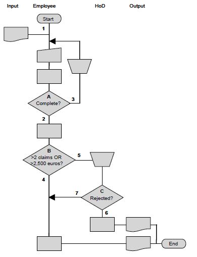
Figure 2: Simplified reproduction of the process diagram.
Check for yourself that application of the coverage type “paths” delivers the following test situations (path
combinations) with test depth level 2:
A: 1-2; 1-3; 3-2; 3-3
B: 2-4; 2-5
C: 5-6; 5-7
2 - Creating logical test cases
The creation of the logical test cases is divided into two activities:
-
Creating a set of logical test cases
-
Describing the consecutive actions per logical test case.
In the creation of the set of logical test cases, all the test situations should be covered. A test case is defined by
going through the process in a certain way from “Start” to “End” (see section Paths). The tester is free to choose the way in which the process is followed, as
long as all the test situations are covered at least once.
Example 3 - For the process of claims handling, the tester arrives at the following set of
logical test cases:
TC1 = 1-2-4
TC2 = 1-2-5-6
TC3 = 1-3-3-2-5-7
Check for yourself that the following set is also one of the possible sets:
TC1 = 1-3-3-2-4
TC2 = 1-2-5-6
TC3 = 1-2-5-7
If test depth level-1 had been used, for example, it would have led to the following set of logical test cases (check
for yourself that several sets are possible here):
TC1 = 1-2-4
TC2 = 1-2-5-6
TC3 = 1-3-2-5-7
The logical test cases should then be written out. This means that for each test case a row of consecutive actions
should be described, in such a way that the execution of these actions will touch on all the test situations from the
test case. This activity requires inventiveness and is therefore rather difficult to describe in general terms. See the
concrete terms of the example.
Example 4 - The tester has described the following actions in respect of TC3
(1-3-3-2-5-7):
A3-1 Create claim form (Insured)
A3-2 Enter claim form details into the system (incomplete) (Employee)
A3-3 Start the process “Check for completeness” (Employee)
A3-4 Contact the insured party to complete the details (Employee)
A3-5 Enter claim form details including one additional detail into the system (incomplete) (Employee)
A3-6 Start the “Check for completeness” process (Employee)
A3-7 Contact the insured party to complete details (Employee)
A3-8 Enter claim form details including additional details into the system (complete, claim sum > €2,500)
(Employee)
A3-9 Start “Check for completeness” process (Employee)
A3-10 Start “Determine number of claims and claim sum” process (Employee)
A3-11 Assess notification of claim (Head)
A3-12 Claim is accepted (Head)
A3-13 Start “Create letter” (approval letter) process (Employee)
A3-14 End process
3 - Creating physical test cases
Besides the previously mentioned differences from the other test design techniques, there is another difference to
note. With the test execution, there is more required in the process cycle test than just the technical test
infrastructure on which the automated part of the information system runs. The manual procedures mainly have to be
carried out by various types of employees, which means that several testers are required to play particular roles in
the test execution. It is of course also possible to have the test executed by one tester who possesses several user
IDs, repeatedly logging in and out during the test execution. In addition, the required data are only partly present in
the database of the automated part of the information system, and the rest is outside the system, for example in the
form of completed forms.
That, too, is different from the other test design techniques. In the creation of the physical test cases, a physical
formulation of the logical test cases is supplied. With this, the actions described serve as a starting point.
Example 5 - The tester has described the physical formulation of TC3 (1-3-3-2-5-7) as
follows:
Insured party:
A3-1 Create claim form with following details:
Name : Janssen, J.
Address : Amsterdamstreet 7, Utrecht
Date of loss : <empty>
Description of loss : <empty>
Cause of loss : Theft from home
Claim sum : €4,250
Employee (EMP_01):
A3-2 Enter claim form details into the system (without “Date of loss” and without “Description of loss”)
A3-3 Start “Check for completeness” process (form is incomplete)
A3-4 Contact insured party to obtain “Date of loss”
A3-5 Enter claim form details in the system (“Date of loss” is 1 December 2006)
A3-6 Start “Check for completeness” process (form is incomplete)
A3-7 Contact insured party to obtain “Description of loss”
A3-8 Enter claim form details in the system (“Description of loss” is “Stolen necklace”)
A3-9 Start “Check for completeness” process (form is complete)
A3-10 Start “Determine number of claims and claim sum” process (claim sum > 2,500, therefore assessment by
HoD)
Head of Department (HEAD_01):
A3-11 Assess notification of claim
A3-12 Accept claim
Employee (EMP_01):
A3-13 Start “Create letter” process (approval letter is created)
A3-14 End process
4 - Establishing the starting point
No remarks.
Example 6 - In order to execute the test cases from the claim example, the following is
necessary:
-
The insurance details pertaining to the insured party must be present in the database
-
The user IDs of an employee and the head of department with relevant authorisation(s) should be known by the system
-
The claim forms must be complete.
As an example, the starting point for TC3 is provided here:
Insurance details:
Name : Janssen, J.
Address : Amsterdamstreet 7, Utrecht
Number of claims in 2006 : 2
User IDs:
The user IDs “EMP_01” and “HEAD_01” should be present in the system with the associated authorisation(s).
Claim form:
Name : Janssen, J.
Address : Amsterdamstreet 7, Utrecht
Date of loss : <empty>
Description of loss : <empty>
Cause of loss : Theft from home
Claim sum : €4,250
|
